
Radiated immunity testing verifies that a product keeps working when exposed to an external electromagnetic field. It is the reverse direction of EMC testing: instead of measuring what the product emits, it measures how well the product tolerates interference. Automotive work follows CISPR 25 and ISO 11452-2.
How the test works
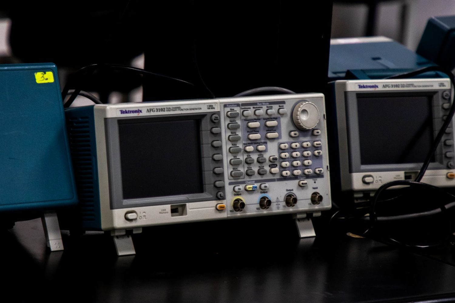
Inside the chamber, a signal generator drives an antenna to establish the specified field strength at the test position. The product operates in that field while its function is monitored continuously. If an anomaly occurs, the judgement position records the exact frequency and the moment of interruption immediately.
Severity levels are set by the standard and are usually expressed as field strength (for example 30 V/m or 100 V/m); some OEM corporate standards impose higher requirements.
Test methods
Chamber field method: field strength applied in a fully or semi-anechoic chamber — the most widely used method.
TEM cell method: a uniform field is generated inside a transverse electromagnetic cell; the environment requirement is lower, but sample size is limited.
Stripline method: suited to field injection testing of cable-like samples such as harnesses and connectors.
Monitoring items and criteria
Function monitoring: whether core functions remain normal — communication not interrupted, display not anomalous, actuators not actuating spuriously.
Performance criterion A: fully normal during and after the test, with no degradation.
Performance criterion B: temporary degradation during the test, self-recovering afterwards; acceptable but must be recorded.
Performance criterion C: requires manual or automatic intervention to recover; must be assessed and recorded.
Performance criterion D: permanent loss of function — a failure.
Common failure modes and corrective action
MCU crash or watchdog reset → insufficient immunity in the reset circuit; add decoupling and filtering.
Communication loss (CAN/LIN) → insufficient bus protection; add TVS devices and common-mode chokes.
Display flicker or image corruption → poor shielding at the LVDS/MIPI interface; add ground shielding and filtering.
ADC sampling drift → the analogue front end is disturbed; move signal lines away from the source and use differential transmission.
Relay spurious operation → the drive signal needs isolation and pull-up/pull-down hardening.
Frequently asked questions
Does immunity testing need to reproduce real-world scenarios?
It does not reproduce real scenarios exactly; it applies the severity defined by the standard. Standard severity levels are industry-accepted empirical values that already cover the immunity needs of real situations. Designing your own scenario tends to deviate from the standard, so results cannot be compared with those of other suppliers.
Does a temporary anomaly during the test count as a failure?
It depends on the performance criterion. Criteria A and B are usually acceptable (self-recovery after the test), criterion C must be assessed and recorded, and criterion D is a failure. The applicable standard or the OEM acceptance requirement governs.
Service notes
Our laboratory holds both CMA and CNAS accreditation, covers about 10,000 m2 and runs more than 500 sets of equipment. All testing is carried out in our own laboratories — nothing is subcontracted. Plant visits and on-site witnessed testing are welcome.
Scheduling follows the actual project pipeline. You can state your preferred lead time when you submit samples; we will confirm a feasible plan against current capacity and keep you updated at each milestone. Once the report is issued we send the electronic copy; corrective-action advice can be arranged separately.
