
Key takeaways
Automotive electronics EMC testing splits into two families: emission (EM) measures the interference a product sends out, and immunity measures how well it withstands external interference. Radiated emission covers the space-coupled path, conducted emission covers the power and signal cable path. Automotive applications mainly follow CISPR 25 and GB 18655.
Automotive EMC testing is inherently two-directional: one direction tests whether your product interferes with other on-board electronics (navigation, radio, communication modules), the other tests whether your product still works when interference is applied to it.
1. Emission testing: the interference a product sends out
Emission testing splits into two paths, and this is the core classification:
Radiated emission
In operation a product radiates electromagnetic waves through housing gaps, cables and antennas. The test runs in a shielded room or anechoic chamber, measuring field strength across the bands with a receiving antenna at a defined distance (1 m, for example).
Typical causes of a limit exceedance: clock lines routed without impedance control, insufficient filtering on the switching supply, poor shielding across board-to-board gaps, badly treated housing seams.
Conducted emission
Interference is conducted out along power and signal lines. The test measures disturbance voltage at the supply end using a LISN (line impedance stabilisation network). Typical causes: harmonics of the DC-DC switching frequency, missing bulk input capacitance, supply ripple exceeding limits in standby.
2. Immunity testing: how well a product resists interference
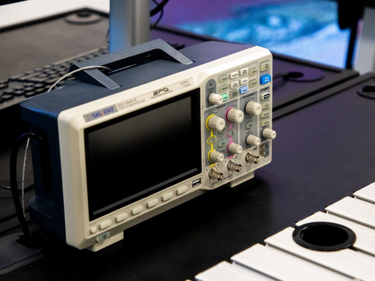
Immunity is the reverse check: apply the disturbance field the standard specifies and see whether the product misbehaves, hangs or produces abnormal output. Common automotive items include:
- Electrostatic discharge (ESD): contact discharge simulates a person touching metal, air discharge simulates touching a key or a button
- Radiated immunity (RI): field illumination from an antenna in the chamber, simulating a high-power transmitter at a distance
- Conducted immunity (CI): pulse disturbance injected through the power network, simulating vehicle start-up and alternator faults
- Surge and transient pulses: simulating load dump, jump-starting and other whole-vehicle transients
3. Which standard applies?
The core basis for automotive electronics EMC is CISPR 25 (international) and GB 18655 (identical adoption). They define the emission limits and immunity test conditions for on-board electronic devices in both the conducted and radiated directions.
If the product is also exported to the EU, ECE R10 is layered on top; OEMs often have stricter corporate standards, and the customer requirement governs during OEM validation.
4. When in development should it be run?
Run a pre-compliance scan as early as the EVT stage. EMC problems usually originate in PCB layout and mechanical design, and the cost of fixing them later rises in multiples. One scan at pre-compliance saves a great deal of rework downstream.
Turnaround time is arranged according to the actual project. You are welcome to state your target date when submitting samples; we will check it against the current schedule, confirm a feasible plan with you, and update you at each milestone.

